
< 1 2 >
Methods of Neutral Grounding
- Solid or effective grounding
- Resistance grounding
- Reactance grounding
- Peterson-coil grounding
Solid or effective grounding
जब 3-phase system (जैसे - phase generator, 3-phase transformer etc.) का neutral point negligible resistance और reactance के एक wire के through directly earth से connected होता है तो इसे solid grounding या effective grounding कहा जाता है ।

figure, में neutral point के solid grounding को shows किया गया है। चूंकि neutral point एक wire through earth से directly connected होता है इसलिए neutral point को सभी conditions में earth की potential पर आयोजित किया जाता है। इसलिए, under fault conditions के तहत, earth के किसी भी conductor का voltage system के normal phase voltage से अधिक नहीं होगा।
Advantages
- neutral रूप से earth की potential पर effectively रूप से आयोजित किया जाता है

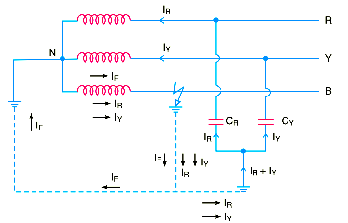
- जब earth पर किसी भी phase में fault होता है तो resultant capacitive current IC fault current IF के phase oppose करता है। two currents एक दूसरे को पूरी तरह से cancel कर देती हैं। इसलिए, कोई arcing ground या over-voltage की conditions नहीं हो सकती है। figure में दिखाए गए अनुसार line B में line to ground fault को consider करते है, healthy phases R और Y में flow होने वाली capacitive currents IR और IY क्रमशः resultant capacitive current IC, IR और IY का phasor sum होता है। इन capacitive currents के अलावा, power source fault current IF की supply भी करता है। यह fault current fault point से earth तक जाएगा, फिर neutral point N से और fault point के through faulty phase तक जायेगा। IC का path capacitive है और IF का inductive है। two currents phase के opposition में है और एक दूसरे को पूरी तरह से cancel कर देती है इसलिए, कोई भी arcing ground का phenomenon या over-voltage की conditions हो सकती है।
- जब system के किसी भी phase पर earth fault होता है, तो faulty phase के earth voltage का phase zero हो जाता है, हालांकि, शेष दो healthy phases के earth voltages के उतार-चढ़ाव का phase normal phase voltage पर रहता है क्योंकि neutral की potential earth के potential के अनुसार fixed की जाती है।
- system को earth fault से बचाना आसान हो जाता है जो अक्सर system पर होते हैं। जब system के किसी भी phase में earth fault होता है, तो fault point और ground neutral के बीच एक large fault current flows होती है। यह earth fault relay के easy operation की अनुमति देता है।
Disadvantages
- चूंकि overhead system के अधिकांश faults earth के faults के phase है इसलिए सिस्टम को large number में गंभीर shocks झेलने पड़ते हैं। इससे system unstable हो जाता है।
- solid grounding के परिणामस्वरूप heavy earth fault currents होता है। चूंकि circuit breakers, द्वारा fault को clear किया जाना है, इसलिए heavy earth fault currents circuit breaker contacts के जलने का कारण हो सकता है।
- neighbouring की communication lines में अधिक से अधिक interference के कारण earth के fault current का results होता है
Applications
Solid grounding आमतौर पर नियोजित किया जाता है जहां circuit impedance पर्याप्त रूप से high होती है ताकि safe limits के भीतर earth fault को चालू रखा जा सके। grounding की इस system का उपयोग 33 kV तक की voltages के लिए किया जाता है जिसमें total power capacity 5000 kVA से अधिक नहीं होती है।Resistance grounding
जब 3-phase system (जैसे - 3- phase generator, 3-phase transformer आदि ) का neutral point एक resistor के माध्यम से earth से connected होता है, तो इसे resistance grounding कहा जाता है।

Figure में एक resistor R के माध्यम से neutral point की grounding दिखाता है। R का value न तो बहुत कम होना चाहिए और न ही बहुत अधिक होना चाहिए। यदि earthing resistance R का मान बहुत कम है तो earth fault current large होगा और system solid grounding system जैसा हो जाएगा।
दूसरी ओर, यदि earthing resistance R very high है तो system की conditions
ungrounded neutral system के समान हो जाती हैं। R का value इतना चुना जाता है कि earth fault current safe value तक सीमित रहता है, लेकिन फिर भी earth fault protection system के operation की अनुमति देने के लिए पर्याप्त है। practice में R का वह value चुना जाता है जो earth के fault generator or transformer के normal full load current से earth fault को 2 गुना तक सीमित कर देता है।
Advantages of Resistance grounding
- R के value को adjust करके, arcing grounds को minimised किया जा है मान लीजिए कि phase B में earth fault होती है जैसा कि figure में दिखाया गया है। capacitive currents IR और IY क्रमशः healthy phases R और Y में flow होती है। fault current IF यदि earthing resistance R के base पर एक निश्चित angle द्वारा fault phase के phase voltage से lags करता है और system के reactance को fault के point तक ले जाता है। fault current IF को two components में resolved किया जा सकता है।
(a) faulty phase voltage के साथ phase में IF1 (b) IF2 90° तक faulty phase voltage से lagging है
- earthing resistance की उपस्थिति के कारण earth fault current small होता है। इसलिए, communication circuits के साथ interference कम हो जाता है।
- यह system की stability को improve करता है

Disadvantages of Resistance grounding
- चूंकि earth fault, के दौरान system neutral displaced हो जाता है, इसलिए higher voltages के लिए equipment insulate करना पड़ता है।
- यह system solidly grounded system की तुलना में महंगी है।
- earth fault के दौरान earthing resistance में large amount में energy का उत्पादन होता है। कभी-कभी energy को atmosphere में फैलाना मुश्किल हो जाता है।
Applications of Resistance grounding
इसका उपयोग 5000 kVA से अधिक power source capacity वाले 2.2 kV और 33 kV के बीच voltage पर काम करने वाले system पर किया जाता है।
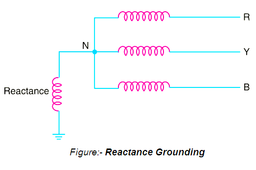
Reactance grounding :-
इस system में, neutral और ground के बीच एक reactance insert की जाती है जैसा कि figure में दिखाया गया है। reactance का purpose earth fault current को limit करना है। earthing reactance को change करके solid grounding के समान conditions को प्राप्त करने के लिए earth fault current को changed किया जाता है

इन method का उपयोग इन disadvantages के कारण नहीं किया जाता है:

इन method का उपयोग इन disadvantages के कारण नहीं किया जाता है:
- इन system में, protective device को operate करने के लिए required fault current same fault के conditions के लिए resistance grounding से अधिक होता है।
- High transient voltages की under fault conditions में appear होते है।
Peterson-coil grounding /Arc Suppression Coil Grounding/Resonant Grounding) :-
हमने देखा है कि capacitive currents arcing grounds के producing के लिए responsible है। ये capacitive currents flow होती हैं क्योंकि प्रत्येक line और earth के बीच capacitance exists होता है। यदि appropriate value inductance L system के capacitance के parallel से connected होता है तो L के through से flow होने वाला fault current IF system के capacitive current IC के oppose में होगा। यदि L इतना adjust होता है कि IL = IC, तो fault में resultant current zero होगा। इस condition को resonant grounding के रूप में जाना जाता है।
जब arc suppression coil के L का value ऐसा होता है कि fault current IF यदि
capacitive current IC को balance करता है, तो इसे resonant grounding कहा जाता है।
Circuit details:-
arc suppression coil (जिसे Peterson coil भी कहा जाता है) एक iron-cored coil है जो neutral और earth के बीच connected है जैसा कि figure में दिखाया गया है। reactor को coil के inductance को change के लिए टेपिंग के साथ provided किया जाता है। coil पर tappings को adjust करके, coil को system के capacitance के साथ tuned किया जा सकता है यानी resonant grounding प्राप्त किया जा सकता है।
Operation:-
Figure (i) 3-phase system से पता चलता है कि Peterson coil grounding को नियोजित करता है। मान लीजिए कि line to ground fault point F पर line B में होता है। fault current IF और capacitive currents IR और IY जैसा कि figure (i) में दिखाया गया है। figure (i) ध्यान दें कि यदि IF Peterson coil (या Arc suppression coil) के through flow होता है तो, fault के through से neutral और वापस आ जाता है। total capacitive current IC, IR और IY का phasor sum है जैसा कि phasor diagram, Figure (ii) में दिखाया गया है। faulty phase के voltage को arc suppression coil के across applied किया जाता है। इसलिए, fault current IF faulty phase voltage को 90° lag कर देता है। current IF, capacitive current IC के phase oppose में है। See Figure (ii) Peterson coil पर tappings को adjust करके, fault में resultant current को
reduce किया जा सकता है। यदि coil का inductance इतना adjust है कि IL = IC, तो fault में resultant current zero होगा।
Advantages of Reactance grounding:-
- Peterson coil एक arcing ground द्वारा किसी भी damage को रोकने में पूरी तरह से effective है।
- Peterson coil में ungrounded neutral system के advantages है
Disadvantages of Reactance grounding:-
- varying operational conditions के कारण, network की capacitance time to time change होते रहती है। इसलिए, Peterson coil के inductance L को readjustment की आवश्यकता होती है।
- lines को transposed किया जाना चाहिए।


0 Comments